
Sheet Metal Deburring – Methods, Process Workflow & Quality Control

Laser cutting, punching, plasma cutting, and oxy-fuel cutting all create burrs along sheet metal edges. These burrs are a physical result of the cutting process and can affect every downstream operation. Proper deburring improves workplace safety, coating durability, and reliable downstream processing.

This guide explains which deburring methods are best suited for different materials and cutting processes, how the workflow progresses from slag removal and deburring to edge rounding, and how to achieve consistent, repeatable quality. It also examines when machine-based or fully automated deburring becomes economically viable.

Custom Request To Deburring Machines

Key Takeaways

  • Burrs are unavoidable: Every cutting process—laser, plasma, punching, and oxy-fuel cutting—creates excess material along the cut edge. This is physically unavoidable.
  • 6 reasons to deburr: Workplace safety, coating quality, tool protection, reliable downstream processing, product safety, and cost efficiency.
  • Process workflow: Slag removal → pre-grinding → deburring → edge rounding → surface finishing. Not every application requires every step.
  • Methods: Mechanical grinding is the industry standard. Shot blasting combines deburring and descaling. Mass finishing is ideal for small parts. Manual deburring is expensive and produces inconsistent quality.
  • Edge rounding is essential: A minimum radius of R 0.2 mm is required before coating. Only a defined radius prevents the electrostatic edge effect during powder coating.
  • Cost per part: Manual: approx. €2.50–4.00 per part · Through-feed machine: approx. €0.30–0.60 · Automated: approx. €0.10–0.20. Typical machine ROI: 12–24 months.
  • The material determines the process: Thin sheet → wide belt + brush; heavy plate and flame-cut parts → slag hammer + roller; stainless steel → wet grinding + finishing; aluminum → vacuum table + ATEX-rated system.
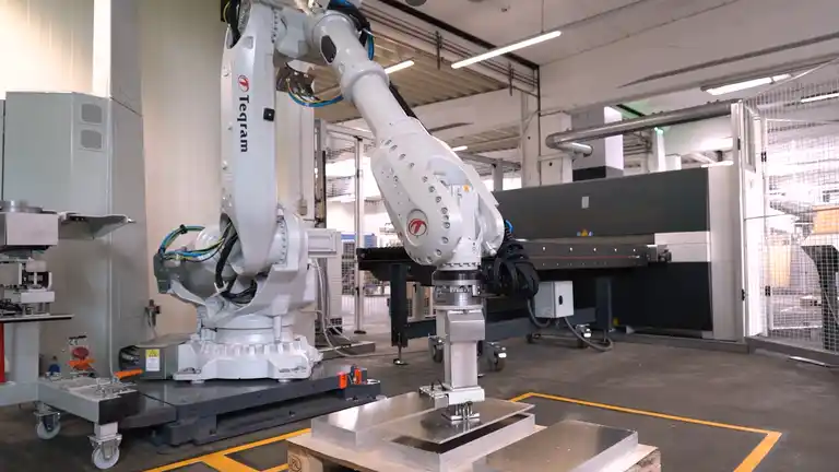
  • Automation becomes worthwhile at approximately 10 parts per week. Vision-guided robotic systems, such as Teqram, require no teaching—even with changing geometries and batch sizes.
  • Time savings of up to 60%: Double-sided machines deburr the top and bottom in a single pass—no flipping, less handling, and lower costs. Quality can be verified through visual, tactile, and automated 3D vision inspection.

Every sheet metal part that is sawed, punched, laser-cut, or thermally cut will have burrs afterward. These protrusions along the cut edges are a physically unavoidable result of the process—and removing them professionally directly affects workplace safety, coating quality, and the cost efficiency of every downstream operation.

This guide explains how burrs form, which processes and machine units are available, when machine-based deburring becomes cost-effective, and when automation makes economic sense.

How Do Burrs Form on Sheet Metal?

A burr is not a manufacturing defect—it is a physically unavoidable result of the cutting process.

Mechanical Cutting Processes

During punching and shearing, the tool plastically displaces the material. Localized material fracture creates a sharp, pointed primary burr along the cut edge. Dull cutting edges or excessive cutting clearance significantly increase burr formation.

  • Caused by plastic deformation
  • Burr forms on one side of the part (punch exit side)
  • Burr size depends on tool condition and cutting clearance
  • Typical burr height: 0.002–0.020 in (0.05–0.5 mm)

Thermal Cutting Processes

During laser, plasma, and oxy-fuel cutting, the material melts and exits through the cutting kerf. It solidifies as a bead-like buildup along the bottom edge. Thermal cutting processes also create an oxide layer along the cut surface.

  • Solidified molten material along the edge
  • Plasma and oxy-fuel cutting: additional slag
  • Oxygen-assisted laser cutting: oxide layer on the cut surface
  • Typical burr height: 0.004–0.315 in (0.1–8 mm), depending on the process

Primary vs. Secondary Burrs – What’s the Difference?

  • Primary burr - Forms directly during the cutting process as excess material along the cut edge.
  • Secondary burr - Can form during pre-grinding and lies close to the surface. It is removed during the deburring and edge-rounding process.

Request your Automated Sheet Metal Deburring Solution

ContactBot_Teqram_1000x1000

Upload any relevant sketches, drawings, or other supporting documents here

Burr Types by Cutting Process

Cutting Process Burr Type Typical Burr Height Key Characteristics
Laser Cutting Narrow and pointed 0.004–0.020 in (0.1–0.5 mm) More pronounced with aluminum and thicker material; oxide layer when cutting with O₂
Plasma Cutting Bead-like buildup 0.020–0.118 in (0.5–3 mm) Additional oxide and scale layers; hardened edge zone
Oxy-Fuel Cutting Heavy burr with slag 0.039–0.315 in (1–8 mm) Solidified molten material adheres firmly; slag must be removed before deburring
Punching Sharp cut-edge burr 0.002–0.020 in (0.05–0.5 mm) Forms on one side of the part (punch exit side); depends on cutting clearance
Waterjet Cutting Minimal or no burr 0–0.004 in (0–0.1 mm) The rough cut surface may still require secondary finishing
Milling / Sawing Chip-like burrs Variable Burrs form at tool entry and exit; worn tools increase burr formation

6 Reasons Why Deburring Is Essential

Burrs on sheet metal parts are more than a cosmetic issue—they affect safety, cost, quality, and every downstream manufacturing process.

1. Workplace Safety

Sharp sheet metal edges are a common cause of injuries in metalworking operations. Cuts can occur during handling, assembly, and use by the end customer. Protective gloves provide only limited protection against very fine, sharp burrs.

2. Coating Quality

During powder coating and e-coating, electric field lines concentrate at sharp points, similar to a lightning rod. Coating builds up unevenly on burr tips while remaining too thin on adjacent surfaces. The result is premature chipping and corrosion.

3. Tool Protection

Burrs can damage press brake tooling, leveling rollers, and precision milling tools. In roller leveling machines, burrs can press into the rollers and leave marks on every part processed afterward, resulting in costly secondary damage.

4. Downstream Processing

Parts with burrs are more difficult to join and bend. Oxide layers and slag interfere with welding. When parts are stacked, burr tips can scratch adjacent sheet metal surfaces, leading to scrap and rework.

5. Product Safety

A detached burr inside a finished product can cause mechanical damage or electrical short circuits. In the automotive, machinery, and medical technology industries, burr-free sheet metal edges are not optional—they are a quality and compliance requirement.

6. Cost Efficiency

Deburred parts measurably reduce rework, scrap, and customer complaints. Clean edges simplify assembly and reduce the time required for every downstream step in the sheet metal manufacturing process.

The Sheet Metal Deburring Process

Deburring is rarely a single operation. Depending on the initial condition of the sheet metal part, the process may include up to five coordinated steps.

1
Slag Removal

Required only for plasma-cut and oxy-fuel-cut parts

2
Pre-Grinding

Reduce primary burrs and level the surface

3
Deburring

Completely remove excess material

4
Edge Rounding

Create a radius of 0.008–0.079 in (R 0.2–R 2 mm)

5
Surface Finishing

Optional: uniform finish and oxide removal

1. Slag Removal (Plasma-Cut and Oxy-Fuel-Cut Parts Only)

Plasma-cut and oxy-fuel-cut sheets often have solidified molten beads and slag deposits along the bottom edge. These must be removed before deburring. Otherwise, the hard slag interferes with tool engagement and can significantly damage grinding units. In through-feed machines, slag-hammer brushes with flexibly mounted pins perform this step efficiently.

2. Pre-Grinding

Pre-grinding prepares the sheet metal edge for the actual deburring process. It reduces primary burrs in a controlled manner, levels surface irregularities, and creates a consistent starting point for subsequent operations. Without this step, deburring tools encounter uneven edges, resulting in unstable tool engagement, increased wear, and inconsistent quality.

Tool Application
Coated Abrasive Belts Leveling surfaces and uniformly removing primary burrs
Hook-and-Loop Sanding Discs Localized excess material and changing contours
Abrasive Stars Complex contours, tubes, profiles, and confined areas
Flap Wheels High material removal rates for heavy primary burrs

3. Deburring

The deburring process removes any remaining excess material and creates a clean, consistent edge geometry. Pre-grinding can also create a secondary burr by plastically displacing material toward the surface. This secondary burr is removed along the part contour during deburring. Different processing units are used depending on the cutting process, material thickness, and finish requirements.

4. Edge Rounding

Edge rounding transforms a sharp cut edge into a defined radius. Modern through-feed machines integrate this step into the same machine pass, adding virtually no extra processing time. A properly rounded edge improves long-term coating adhesion, supports safer assembly, and helps meet applicable quality standards.

R 0.008 in
Minimum radius for powder-coating adhesion (R 0.2 mm)
R 0.079 in
Maximum standard radius (R 2.0 mm)
1 Pass
Processes both sides in a single pass

5. Surface Finishing (Optional)

When higher cosmetic standards are required—for visible components, stainless steel parts, or export products—a surface-finishing step can be added. This creates a uniform finish and completely removes any remaining heat tint or oxide layers. Glass-bead blasting is a commonly used finishing method for stainless steel after deburring.

Teqram Deburring Machines

Automated Sheet Metal Deburring for Parts up to 1,300 lbs — No Programming. No Teaching.

Custom Request To Deburring Machines

Deburring Methods at a Glance

The right method depends on the material, thickness, type of burr, and production volume.

Mechanical Grinding

  • Suitable for all commonly used metals
  • Consistent, repeatable results
  • Can be combined with edge rounding
  • Available for both through-feed and individual part processing
  • Wet or dry grinding options
  • Wide range of grinding units available

Abrasive Blasting

  • Deburring and descaling in a single step
  • Provides uniform treatment across the entire surface
  • Suitable for virtually any sheet thickness
  • Thin material must be evaluated for warping
  • Ideal for removing rust and mill scale

Vibratory Finishing

  • Parts and abrasive media are processed in a rotating drum
  • Ideal for high-volume production of small parts
  • Limited to parts up to approximately 8 inches
  • Uniform results and highly cost-effective
  • No individual part positioning required

Manual Deburring

  • Files, angle grinders, hand-held deburring tools, or blades
  • Suitable for one-off parts and complex shapes
  • Inconsistent quality and high labor costs
  • Rarely cost-effective in high-wage countries
  • Increases the risk of workplace injuries

Thermal and Electrochemical Deburring

  • Thermal: combustible gas removes burrs through controlled combustion
  • Electrochemical: burrs are removed through anodic metal dissolution
  • Cryogenic: liquid nitrogen and blasting media are used
  • Rarely used in sheet metal fabrication
  • More common in precision engineering and medical manufacturing

Wet vs. Dry Deburring: Which Is Right for Your Application?

Dry deburring is the standard method because it is easier to operate and requires less complex equipment. Grinding dust produced when processing steel must be properly extracted because it is combustible, and residual slag may continue to smolder. Wet grinding prevents airborne dust, cools the grinding area, and reduces heat discoloration on stainless steel. Aluminum requires either wet grinding or an ATEX-certified dust extraction system because aluminum dust is explosive. Thin aluminum sheet also requires a vacuum table or an adhesive conveyor belt. Otherwise, the grinding force can cause parts to shift or be thrown through the machine.

Deburring Machine Tools and Processing Units

Modern through-feed deburring machines combine multiple processing units in a single pass. Each unit has its own strengths and is designed for specific applications.

Processing Unit Application Best Suited For

Wide-Belt Grinding Unit

Burr removal—the most common configuration—with P60–P120 grit Laser-cut and punched parts from 0.020–0.47 in. (0.5–12 mm)

Deburring Roller

High contact pressure for heavy burrs on thick plate, using P40–P80 grit Flame-cut parts and plate thicker than 0.4 in. (10 mm)

Double-Sided Grinding Blocks

Processes the top and bottom in a single pass and accommodates warped parts Parts with burrs on both sides that cannot be flipped

Rotary Brushes

Contour-following edge rounding from 0.012–0.079 in. (R 0.3–R 2 mm), on both internal and external edges Edge rounding on complex part geometries

Slag Removal Unit

Knocks off slag and molten metal deposits as the first processing step Preprocessing plasma-cut and flame-cut parts

Finishing Belt / Nonwoven Roller

Produces a uniform surface finish and removes heat discoloration Stainless steel, visible surfaces, and parts requiring coating preparation

Multiple Processes in a Single Pass

Professional through-feed deburring machines typically combine two to four processing units in a single machine. A common setup for laser-cut parts combines a wide-belt grinding unit for burr removal with rotary brushes for edge rounding—all in one pass, on both sides, with no manual flipping required. For flame-cut parts, a slag removal unit is added as the first processing step.

Teqram Deburring Machines

Automated Sheet Metal Deburring for Parts up to 1,300 lbs — No Programming. No Teaching.

Custom Request To Deburring Machines

Steel & Light-Gauge Sheet: 0.020–0.24 in. (0.5–6 mm)

Thin steel and light-gauge sheet—especially after laser cutting or punching—often have small but extremely sharp burrs. These parts are also sensitive to mechanical force and may warp if excessive pressure is applied.

Recommended

  • Wide-belt grinding unit for burr removal
  • Rotary brushes for edge rounding
  • Double-sided processing in a single pass
  • Fine- to medium-grit abrasives: P80–P120

Key Considerations

  • Set the correct contact pressure
  • Dust extraction is required because steel grinding dust is combustible
  • Film-coated sheet requires dedicated process settings

Heavy Plate & Flame-Cut Parts: 0.4 in. (10 mm) and Thicker

Thicker plate—often plasma-cut or oxy-fuel-cut—typically has heavy burrs, slag deposits, and raised dross. This places significantly greater mechanical demands on the deburring tools. Lead-in tabs and the heat-affected zone (HAZ) may require additional processing steps.

Recommended

  • Slag removal unit as the first processing step
  • Deburring roller for heavy burrs
  • Double-sided grinding blocks to eliminate manual flipping
  • Coarse-grit abrasives: P40–P60

Key Considerations

  • The HAZ may be hardened and require specialized tooling
  • Lead-in removal may require an EasyGrinder
  • Automation provides safer handling of heavy parts

Stainless Steel: 304 / 316

Stainless steel requires special attention. Heat discoloration must either be prevented or removed, and the surface must be protected from contamination by ferrous particles that can cause rust. A consistent grain finish is essential for exposed and cosmetic surfaces.

Recommended

  • Wet grinding to reduce heat discoloration
  • Finishing belt for a consistent grain pattern
  • Glass-bead blasting for the final finish
  • Dedicated equipment separate from carbon steel processing

Key Considerations

  • Prevent cross-contamination from carbon steel particles
  • Remove the oxide layer created by oxygen-assisted laser cutting
  • Higher-quality abrasives are required

Aluminum

Aluminum is soft and tends to clog abrasive media. Because aluminum parts are lightweight, grinding forces may cause them to shift or be thrown through the machine. Aluminum dust is explosive and must be captured using an appropriately rated dust collection system.

Recommended

  • Vacuum table or adhesive conveyor belt
  • Open-coat, anti-loading abrasive belts
  • Wet grinding or explosion-rated dust extraction
  • Rotary brushes for edge rounding

Key Considerations

  • Aluminum dust requires proper explosion protection
  • Do not use belts previously used on carbon or stainless steel
  • Abrasives load quickly, so monitor abrasive life carefully

Deburring by Cutting Process

The cutting process determines the type and size of the burr, as well as any related surface effects—and therefore the most effective deburring strategy.

Cutting Process Burr Type and Characteristics Recommended Process
Laser Cutting Narrow, sharp burrs and an oxide layer when cutting with oxygen Wide-belt grinding followed by a brush unit. Add an oxide-removal brush for oxygen-cut parts.
Plasma Cutting Heavy, raised dross, scale, and a hardened edge zone Slag removal unit → deburring roller → brush unit.
Oxy-Fuel Cutting Heavy burrs, slag, and a heat-affected zone EasyGrinder for slag removal, HAZ removal, beveling, surface blasting, and needle peening.
Punching Cutting-edge burr on one side of the part Wide-belt grinder or brushing machine. Single-sided processing is often sufficient.
Waterjet Cutting Minimal to no burr Brush unit for a 0.008 in. (R 0.2 mm) edge radius before coating.
  • With as few as 10 similarly shaped parts per week, a through-feed machine can pay for itself within 12–24 months compared with manual deburring. For varying batch sizes, heavy parts weighing 66 lb (30 kg) or more, or double-sided processing, an automated loading and unloading system can become cost-effective at approximately 200–500 parts per day. Teqram’s vision-guided robotic systems identify parts without any teach-in—even when part geometries and batch sizes change. No Programming. No Teaching.

  • Single-sided machines accommodate a wider range of parts and generally provide more consistent edge rounding, but parts must be flipped manually to process the second side. Double-sided machines are more efficient because they eliminate the flipping step, but they offer less flexibility across different part sizes and geometries. One important limitation: short parts measuring less than approximately 6 in. (150 mm) often cannot be processed in double-sided machines without additional equipment or special handling.

Deburring: An Essential Step Before Powder Coating

Parts must be deburred and their edges rounded before powder coating. This is not an optional quality measure—it is a physical requirement for proper coating performance.

The Lightning Rod Effect

During powder coating and electrocoating, both the coating material and the workpiece are electrostatically charged. Electric field lines concentrate around sharp points and edges—much like they do around a lightning rod. Coating builds up unevenly around sharp burrs, while adjacent surfaces may receive insufficient coverage.

  • Sharp edges create weak points in the coating
  • Chipped or flaking coating dramatically accelerates corrosion
  • The same principle applies to galvanizing and liquid paint

Edge Radius Makes the Difference

Because of the underlying physics, coating thickness is always lowest at the edge. A controlled edge radius of at least 0.008 in. (R 0.2 mm) allows the coating to build more evenly. Deburring also creates a slightly roughened surface, which improves coating adhesion and, in many applications, can eliminate the need for abrasive blasting as a separate pretreatment step.

  • 0.008 in. (R 0.2 mm): minimum edge radius for reliable powder-coat adhesion
  • Double-sided edge rounding in a single pass
  • Textured surface for improved coating adhesion
  • May eliminate abrasive blasting as a pretreatment step

Light-Gauge Sheet – Heavy Plate – Stainless Steel – Aluminum

Each material has its own processing requirements. The right settings make all the difference in the final quality.

Coating Process Minimum Edge Radius Physical Reason
Powder Coating 0.008–0.020 in. (R 0.2–0.5 mm) Electric field lines concentrate around sharp points and edges
Cathodic Electrocoating (E-Coat) 0.012–0.020 in. (R 0.3–0.5 mm) Ensures more uniform coating deposition
Hot-Dip Galvanizing 0.020–0.040 in. (R 0.5–1.0 mm) Promotes consistent zinc coverage along the edge
Liquid Painting 0.008 in. (R 0.2 mm) Reduces the risk of film failure at sharp, 90-degree edges
Electroplating 0.012 in. (R 0.3 mm) Promotes a more uniform coating thickness

Real-World Results from Contract Manufacturing

Double-sided machine deburring with simultaneous edge rounding to 0.008 in. (R 0.2 mm) can often eliminate abrasive blasting as a separate pretreatment step before powder coating. The process cleans and textures the surface at the same time, reducing both processing steps and costs.

For steel and aluminum with a two-coat system and iron phosphate pretreatment, performance level IV—equivalent to 1,000 hours of salt spray testing—can be achieved.

Quality Control, Industry Requirements, and Selection Guidance

If deburring is part of your process, the results must be measured and verified. Certain industries also have specific quality and compliance requirements.

Visual Inspection

The simplest method is a visual inspection under proper lighting. Burrs and sharp edges are often visible, but visual inspection alone is not sufficient for production runs.

Tactile Inspection

A touch probe or manual inspection with protective gloves can detect remaining burrs on internal and external contours. This method is less reliable for very small or thin burrs.

Automated Inspection

3D vision systems automatically detect burrs and surface irregularities. In modern production lines, these systems are installed directly downstream from the deburring machine.

Coating Processes and Their Minimum Requirements

Maintaining Dimensional Accuracy

Machine deburring must not alter a part’s critical dimensions. Professional deburring machines are designed to remove burrs and sharp edges without changing the part geometry. ISO 9001-certified manufacturers document and verify the deburring process as part of their quality management system. With manual deburring, dimensional accuracy depends heavily on the operator and is difficult to reproduce consistently.

Deburring by Industry — Special Requirements

Industry Special Requirements Preferred Process
Industrial Equipment Manufacturing Dimensional accuracy, consistent edges, and protection of downstream tooling Through-feed machine with wide-belt grinding and brushing units
Automotive Consistent production quality, zero tolerance for residual burrs, and safety-critical requirements Fully automated processing with 100% inline inspection
Medical Device Manufacturing Extremely fine burrs, contamination control, and biocompatibility Electrochemical deburring or vibratory finishing
Food and Pharmaceutical Equipment Hygienic stainless steel finishes with no crevices or hard-to-clean areas Wet grinding followed by electropolishing
Construction and Agricultural Equipment Heavy plate, large burrs, and demanding corrosion-protection requirements Slag removal unit, deburring roller, and e-coating
Aerospace Aluminum alloys, extremely high precision, and strict certification requirements Rotary brushes, vacuum workholding, and explosion-rated dust extraction
Prototype Manufacturing One-off parts, frequently changing geometries, and maximum flexibility Manual deburring or a compact brushing machine

Abrasive Grit Selection: Which Grit for Which Application?

Grit Size Grade Application
P24–P40 Extra Coarse Slag removal, heavy burrs on flame-cut parts, and aggressive material removal
P60–P80 Coarse Heavy-plate deburring, plasma-cut parts, and large primary burrs
P100–P120 Medium Standard deburring of laser-cut parts, punched parts, and steel components
P150–P180 Fine Light-gauge sheet, aluminum, stainless steel, and surface preparation before coating
P220+ Extra Fine Surface finishing, polished stainless steel, and visible or cosmetic parts

Double-Sided Processing: Up to 60% Faster

Double-sided deburring machines process the top and bottom of each part in a single pass, eliminating manual flipping. In practice, this can reduce processing time by up to 60% compared with running each side separately, while delivering more consistent quality.

Teqram Deburring Machines

Automated Sheet Metal Deburring for Parts up to 1,300 lbs — No Programming. No Teaching.

Custom Request To Deburring Machines
FAQs

Frequently Asked Questions

  • Sheet metal deburring removes unwanted material—known as burrs—that remains after laser cutting, punching, plasma cutting, or oxy-fuel cutting. The goal is to produce a clean, burr-free edge that is safe to handle and properly prepared for downstream operations such as bending, welding, coating, and assembly.

  • Mechanical deburring with a wide-belt unit in a through-feed machine is the industry standard for laser-cut sheet metal parts. When combined with a brush unit, burr removal and edge rounding are completed in a single pass on steel, stainless steel, and aluminum. If oxygen was used as the cutting gas, the oxide layer should also be removed because it can interfere with coating adhesion and weld quality.

  • Deburring removes excess material from the cut edge to create a clean, even surface. Edge rounding then applies a controlled radius to that edge, such as 0.020 in. (R 0.5 mm). Modern through-feed machines typically combine both steps in a single pass using a wide-belt grinding unit and a brush unit. The additional processing time compared with deburring alone is minimal.

  • Steel, 304 and 316 stainless steel, aluminum, copper, and many other metal alloys can be deburred by machine. Film-protected sheet can also be processed using abrasives and machine settings designed to avoid damaging the protective film. The ideal abrasive grit and cooling method depend on the material. Aluminum also requires open-coat, anti-loading abrasive belts and an appropriately rated dust collection system.

  • At a shop rate of approximately $45–$65 per hour, manual deburring can quickly cost $2.75–$4.50 or more per part. Through-feed machine deburring can reduce that cost to approximately $0.35–$0.70 per part while delivering significantly better and more consistent quality. Fully automated systems can reduce costs to less than $0.25 per part. Depending on production volume and current labor costs, a deburring machine typically delivers a return on investment in less than two years.

  • With as few as 10 similarly shaped parts per week, a through-feed machine can pay for itself within 12–24 months compared with manual deburring. For varying batch sizes, parts weighing 66 lb (30 kg) or more, or applications requiring double-sided processing, automated loading and unloading can become cost-effective at approximately 200–500 parts per day. Teqram’s vision-guided systems identify parts without any teach-in—No Programming. No Teaching.

Teqram Robotic Solutions

Explore our robotic automation solutions below to see which systems could benefit your operation.

Request an Automated Sheet Metal Deburring Solution

ContactBot_Teqram_1000x1000

Upload any relevant sketches, drawings, or other supporting documents here